Transferring a Non-Linear Load Between Phases in a LV Network
The question
Single-phase loads are often moved between phases to rebalance a LV feeder, and some devices do it automatically. When the load is a rectifier with a capacitive DC bus, as most electronic loads are, two questions come up: how much does it distort the network, and what does the transfer itself do to the load?
Model
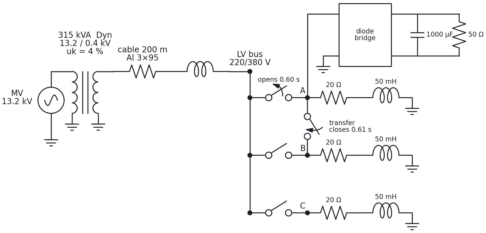
The network is a typical urban LV supply (Figure 1): a 13.2 kV source, a 315 kVA Dyn transformer, 200 m of aluminium cable, and a LV bus with one R-L load per phase. A single-phase full-bridge rectifier with a capacitive DC stage is connected to phase A. At 0.60 s the phase-A switch opens and, at 0.61 s, a transfer switch connects the node to phase B.
| Element | Value |
|---|---|
| MV source | 13.2 kV line-to-line, ideal |
| Transformer | 315 kVA, Dyn, 13.2/0.4 kV, uk = 4 % (R = 6.6 mΩ, L = 0.061 mH referred to LV) |
| Cable | 200 m, Al 3×95 mm²: 0.064 Ω + 0.051 mH per phase (positive sequence) |
| Linear loads | 20 Ω + 50 mH per phase (12.2 A peak, about 1.5 kW each) |
| Rectifier | single-phase full bridge, 1000 µF, 50 Ω (about 1.5 kW) |
| Transfer | phase A opens at 0.60 s; tie to phase B closes at 0.61 s |
| Simulation | 1 µs step, 1 s |
Results
Harmonic content
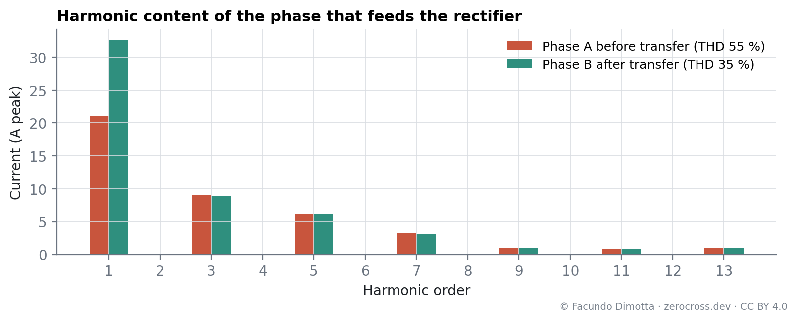
The rectifier only draws current near the voltage peaks. The current of phase A has a fundamental of 21.1 A plus 9.0 A of third, 6.2 A of fifth and 3.2 A of seventh harmonic: a THD of 55 % (Figure 2, Figure 3).
The voltage barely notices. At the LV bus the voltage THD is 0.7 %: with a 315 kVA transformer and 200 m of cable, the network is stiff and the harmonic currents produce small voltage drops.
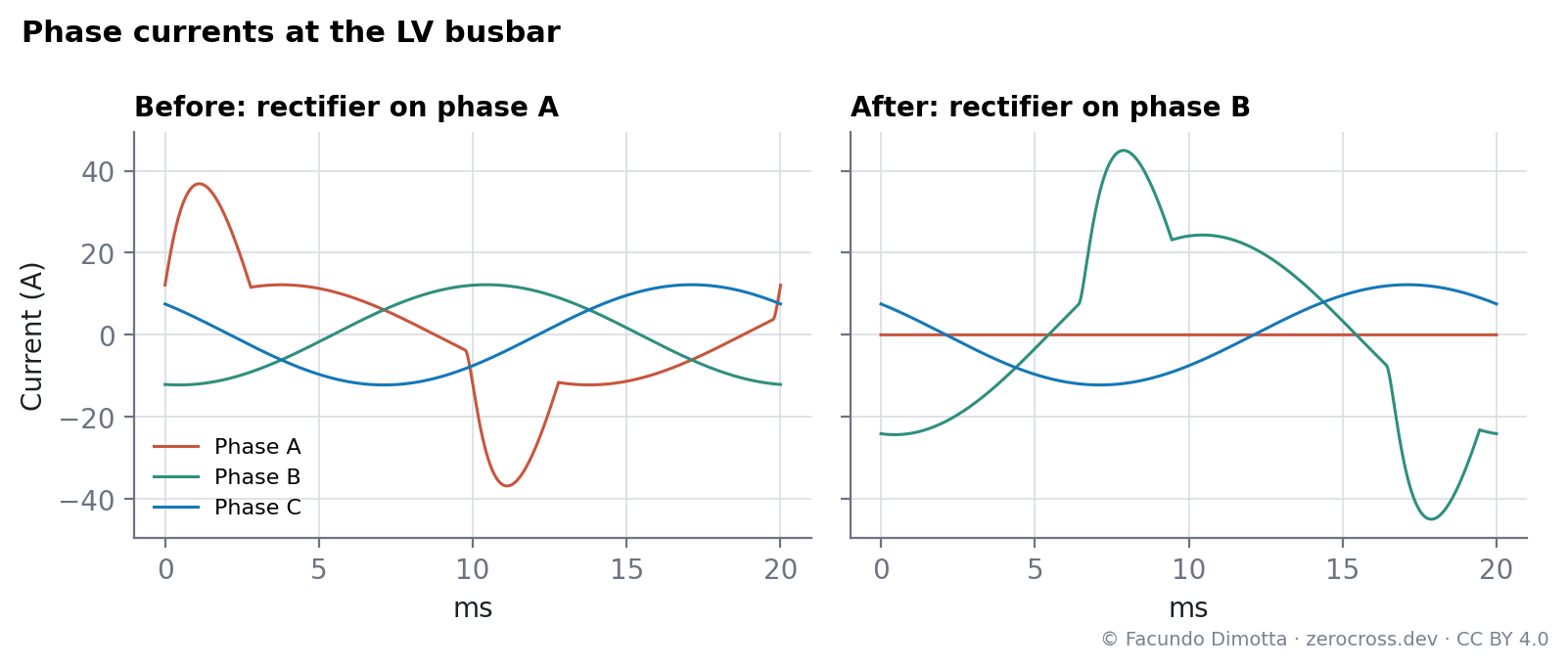
After the transfer, phase B carries its own load plus the transferred one: its current rises from 12.2 A to 32.6 A (fundamental) with a THD of 35 %, and phase A drops to zero.
The transfer itself
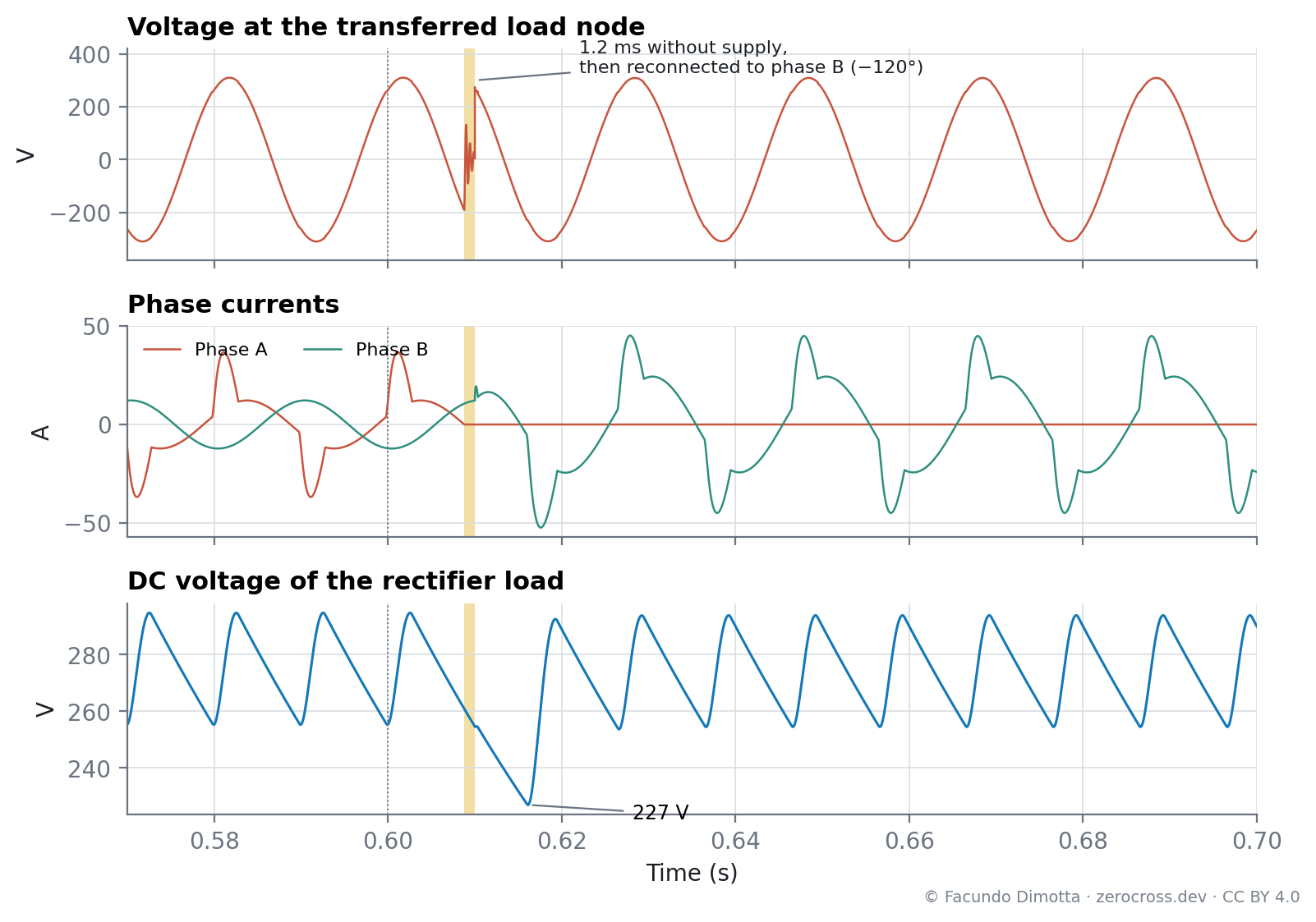
Two details of the transfer only show up in the simulation (Figure 4):
- The switch does not open at 0.60 s. Like a real breaker, the ATP switch interrupts at the next current zero, which comes at 608.8 ms. The load is left without supply for only 1.2 ms.
- What hurts the load is the phase jump, not the interruption. At 0.61 s the node reconnects to a voltage shifted by −120°. The DC capacitor, which only recharges when the supply voltage exceeds its own, keeps discharging until phase B’s voltage catches up. The DC bus falls from its normal 255–295 V ripple to 227 V at 616 ms. The first recharge then draws a 52 A peak from phase B, against 45 A in steady state.
Discussion
- For capacitor-input loads, the reconnection instant matters more than the speed. Interrupting at current zero, as any breaker or static switch does, is clean. The dip comes from reconnecting to a voltage that is, at that instant, below the DC bus voltage. Choosing the reconnection instant, for example when the target phase is near its peak, would reduce both the dip and the inrush.
- The load moves its harmonics with it. In a stiff network the voltage hardly changes, but the current of the receiving phase nearly triples in this case. Automatic phase balancing has to consider both the fundamental and the harmonic content of what it moves.
Limitations
- The MV source is ideal and the cable is modeled with positive-sequence parameters only.
- Switches are ideal: they open at current zero, with no arc.
- During the 1.2 ms without supply, the isolated node shows numerical ringing in the voltage trace; it does not affect the rest of the results.
- One rectifier and one transfer event; aggregate effects of many loads were not studied.
2026-09-23. Model rebuilt and publication rewritten:
- The previous model had no source or line impedance, fed the rectifier through a 5 µF series capacitor that limited it to about 80 W, and used series RLC branches with 5 µF as “linear” loads, which made them capacitive. It now uses a transformer, a cable and R-L loads with realistic values.
- The previous text described a 10 ms dead time. ATP opens switches at current zero, so the actual interruption is 1.2 ms; the DC dip comes from the phase jump.
- “Microsecond-level control” and “SST” (for solid-state technology) were removed.
- Figures regenerated from the simulation data.
Reuse
Citation
@online{dimotta2026,
  author = {Dimotta, Facundo},
  title = {Transferring a {Non-Linear} {Load} {Between} {Phases} in a
    {LV} {Network}},
  date = {2026-03-10},
  url = {https://zerocross.dev/posts/2026-03-10-non-linear-load-phase-transfer/},
  langid = {en}
}