Why an Unloaded Inverter Rings at 500 Hz, and Why It Doesn’t Stop
The question
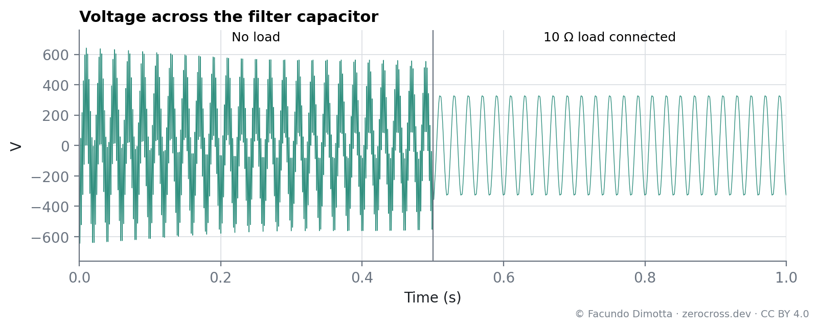
Inverter-based resources (IBR) such as battery storage and PV connect through an output filter. In this model, the inverter runs without load for half a second before a resistor is connected. During that half second the output voltage oscillates at about 500 Hz with peaks of ±640 V, and the oscillation barely decays. Where does it come from, and why does it last?
This is an uncompensated baseline: open-loop modulation and an undamped filter. It is not a general property of inverters operating at low power. Real converters include damping and control precisely to avoid this, and the next study closes the voltage loop.
Model
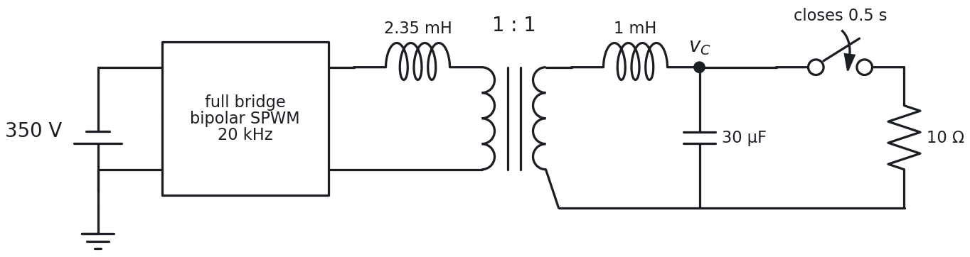
A full bridge fed from 350 V DC is driven by bipolar sinusoidal PWM with a 20 kHz carrier and a modulation index of 1 (Figure 1). Its output goes through an inductor, an ideal 1:1 transformer and a second inductor to a 30 µF capacitor. A 10 Ω load is connected at 0.5 s.
| Element | Value |
|---|---|
| DC source | 350 V |
| Modulation | bipolar SPWM, 20 kHz triangular carrier, m = 1 |
| Filter | 2.35 mH (primary) + 1 mH (secondary) = 3.35 mH; C = 30 µF |
| Parasitic damping | 15 kΩ and 35.25 kΩ across the inductors; 2.5 mΩ in series with C |
| Load | 10 Ω, connected at 0.5 s |
| Simulation | 1 µs step, 1 s |
Results
The resonance
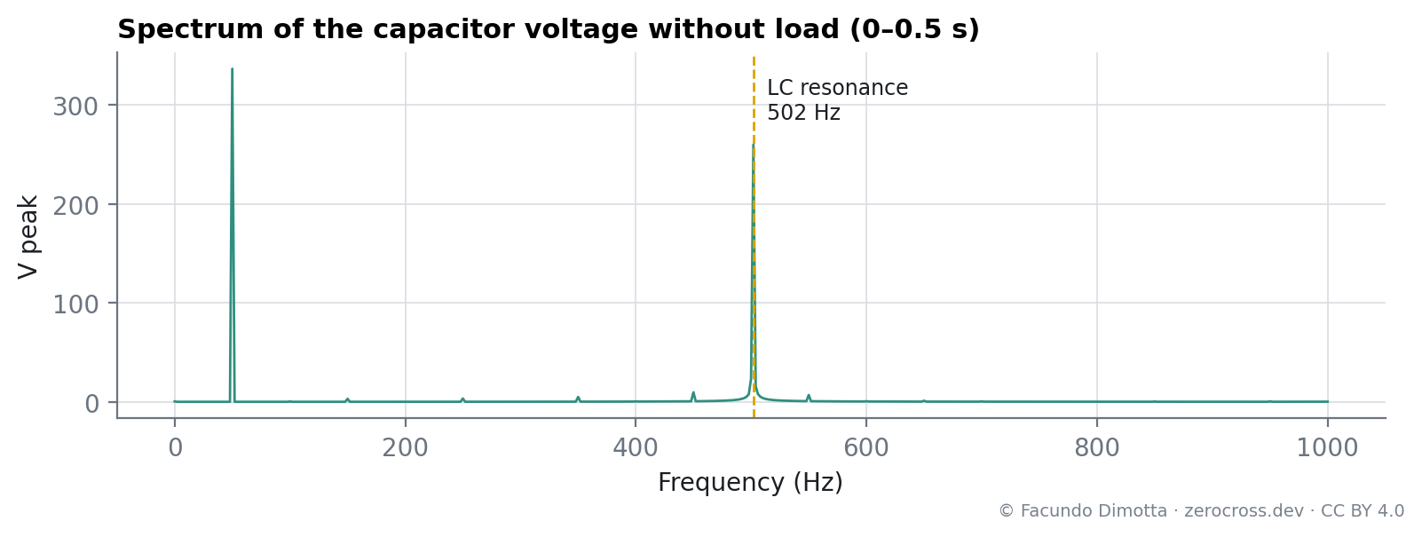
The filter resonance and its characteristic impedance are
f_r = \frac{1}{2\pi\sqrt{LC}} \approx 502\ \text{Hz}
Z_0 = \sqrt{\frac{L}{C}} \approx 10.6\ \Omega .
The spectrum of the capacitor voltage without load has exactly two components: the 50 Hz fundamental and a line at 502 Hz (Figure 2). The oscillation is the filter’s free response, excited when the inverter starts at t = 0 with the filter discharged. The 20 kHz switching is 40 times above the resonance and the filter attenuates it strongly.
Why it doesn’t stop
The only damping comes from the parasitic elements. Referred to a series resistance at 502 Hz they add up to about 4.7 mΩ, which gives
Q = \frac{Z_0}{R} \approx 2200, \qquad \tau = \frac{2L}{R} \approx 1.4\ \text{s}.
With a time constant of 1.4 s, the oscillation should lose about a quarter of its amplitude in 0.4 s. The simulation agrees: the 502 Hz component falls from 289 V to 223 V between the first and the fifth 100 ms window (Figure 3).
What the load does
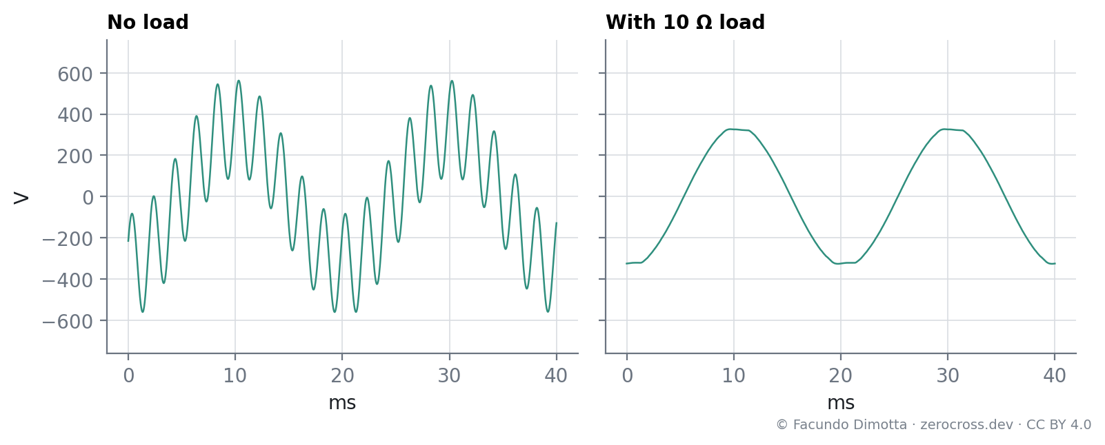
Connecting 10 Ω across the capacitor lowers the quality factor to about R/Z0 ≈ 0.95. The oscillation is gone within a cycle, and the output settles at 335 V peak with a THD of 1.6 % (Figure 4). The peaks flatten slightly because with m = 1 the sine reaches the carrier peak.
Discussion
The severe behavior is not caused by operating at no load. It is the response of an uncompensated converter-filter system: an LC with almost no damping, excited by the start-up and with no control acting on it. Real converters avoid it with some combination of:
- passive damping, a resistor in the filter branch, at the cost of losses;
- active damping, usually feedback of the capacitor current or a virtual resistor in the control;
- soft start, ramping the voltage up instead of applying it at once;
- closed-loop control of the output voltage;
- and, when grid-connected, the damping provided by the grid impedance and other loads.
Which one is needed, and how much, depends on the filter design, the control and the strength of the grid.
Limitations
- Open-loop modulation, ideal DC source and ideal switches.
- The ideal transformer does not model magnetizing current or saturation.
- The result depends on the start-up conditions: a different starting angle or a soft start changes the initial amplitude of the oscillation, not its frequency or decay.
2026-09-23. Rewritten, following comments on LinkedIn that pointed out that the resonance reflects the filter and control design rather than a general limitation of inverter-based resources:
- The system had been described as a solid-state transformer (SST). It is a full-bridge inverter with a low-frequency transformer and an LC filter.
- The oscillation was attributed to the switching harmonics. It is the free response of the filter, excited by the start-up; the resonance frequency (502 Hz), the quality factor and the decay time are now calculated from the model.
- The carrier offset (0.94) left the triangular carrier off-center and produced a small DC component; the carrier is now centered with unit amplitude.
- Figures regenerated from the simulation data.
Reuse
Citation
@online{dimotta2026,
  author = {Dimotta, Facundo},
  title = {Why an {Unloaded} {Inverter} {Rings} at 500 {Hz,} and {Why}
    {It} {Doesn’t} {Stop}},
  date = {2026-05-29},
  url = {https://zerocross.dev/posts/2026-05-29-lc-filter-resonance-no-load/},
  langid = {en}
}